

Overview of Fuse Technology
Portable electronic devices and consumer devices, as well as almost all electronic devices in automotive, military, and aerospace applications, require a certain degree of protection against overcurrent events. The most economical and common overcurrent protection method is the fuse. Eaton offers a wide range of fuses with different configurations and types. When selecting fuses suitable for specific applications, an astonishing number of parameters need to be considered. The fuse technology webpage will review basic fuse operation, application, and selection criteria.
Overcurrent fuses have two main purposes:
·Protect components, equipment, and personnel from the risk of fire and electric shock caused by overcurrent
·Isolate subsystems from the main system after a malfunction occurs
What is an overcurrent event?
When the load on the circuit exceeds the normal load, an overcurrent event occurs. An overcurrent event can be an overload or short circuit state. Components and equipment may be damaged due to two types of overcurrent.
Overload state refers to any current flowing in a circuit that exceeds the normal full load current of the circuit. When overloaded, the current value is usually two to five times the normal operating current of the circuit.
Short circuit state is an overcurrent event that not only deviates from the normal current path, but also significantly exceeds the normal full load current of the circuit (reaching tens, hundreds, or even thousands of times).
Choose overcurrent protection products
Under normal load conditions, fuses must carry the normal operating current of the circuit without encountering disruptive open circuits. However, when overcurrent occurs, the fuse must interrupt the overcurrent and withstand the voltage at both ends of the fuse after internal arcing.
To choose a fuse correctly, the following criteria must be considered:
voltage rating
The rated voltage of the fuse must be greater than or equal to the maximum open circuit voltage. Because fuses have such low resistance, the rated voltage only becomes crucial when the fuse must be opened. The fuse must be able to quickly open, extinguish the arc after the fuse element melts, and prevent the system's open circuit voltage from causing arc reignition on the open circuit fuse element. The rated value of a fuse is determined based on the AC and/or DC circuit voltage it can safely apply.
Normal operating current
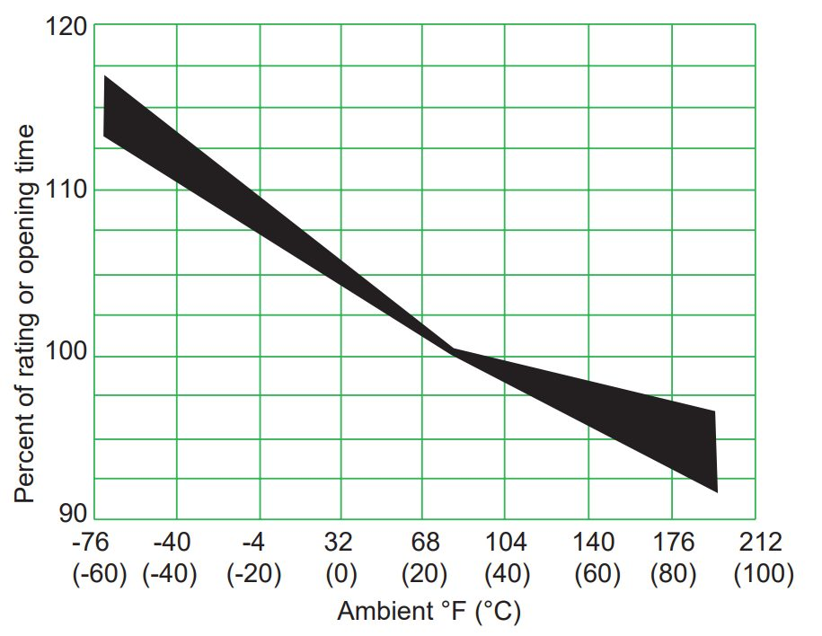
The normal operating current of a circuit refers to the current level (expressed in RMS or DC amperes) drawn by the circuit after being powered on and operating under normal conditions. When working at 25 ° C, it is recommended to use a working current of 80% or lower of the rated current to avoid disruptive open circuits. For example, in circuits with normal operating currents exceeding 800 mA, it is generally recommended not to use fuses with a rated current of 1A. When the ambient temperature rises, further derating is required. The temperature derating curve in the fuse data sheet.
ambient temperature
The ambient temperature refers to the temperature of the air around the fuse, not necessarily room temperature. All electrical characteristics of the fuse are rated and verified at an ambient temperature of 25 ° C. The rise and fall of environmental temperature can affect the open circuit and current carrying characteristics of fuses. The temperature derating curve in the fuse data sheet demonstrates this effect.
Please refer to the product series data sheet and visit www.eaton.com/fuses,Or contact the technical support department for more information.
Overload state and open circuit time.
Please pay special attention to the first overload working point. For fuses, the first overload point is usually between 200% and 300% of the rated current, and 400% is usually the first overload point of the circuit protector. Please refer to the time current curve in the fuse data sheet to ensure that the fuse type meets the circuit requirements.
Available short-circuit current
The fuse must be able to disconnect the circuit in a short circuit state without endangering the surrounding environment. The breaking capacity or rated breaking value of a protective device refers to the maximum available current that the device can safely open circuit (without breakdown) at rated voltage. The breaking capacity or rated breaking value of the fuse must be equal to or greater than the available short-circuit current of the circuit.
Circuit Breaker Integral (I2t)
The melting integral of a fuse (usually referred to as I2t) refers to the thermal energy required to melt a specific fuse component. This value is determined by the construction, material, and cross-sectional area of the fuse element. Each fuse series and ampere rating uses different materials and component configurations, therefore, the I2t value of each fuse must be determined. To determine the I2t of the fuse, it is necessary to test the rated current (time constant less than 50 microseconds) in a DC test circuit. By using a high-speed oscilloscope and integrated program, very accurate I2t values can be measured. The I2t data depicted in the time current diagram (Figure 1).
Circuit designers can use multiple values, including fuse melting I2t, to select fuses and determine appropriate capacity sizes for specific applications. This value can be compared with the thermal energy generated by transient surge currents in the circuit.
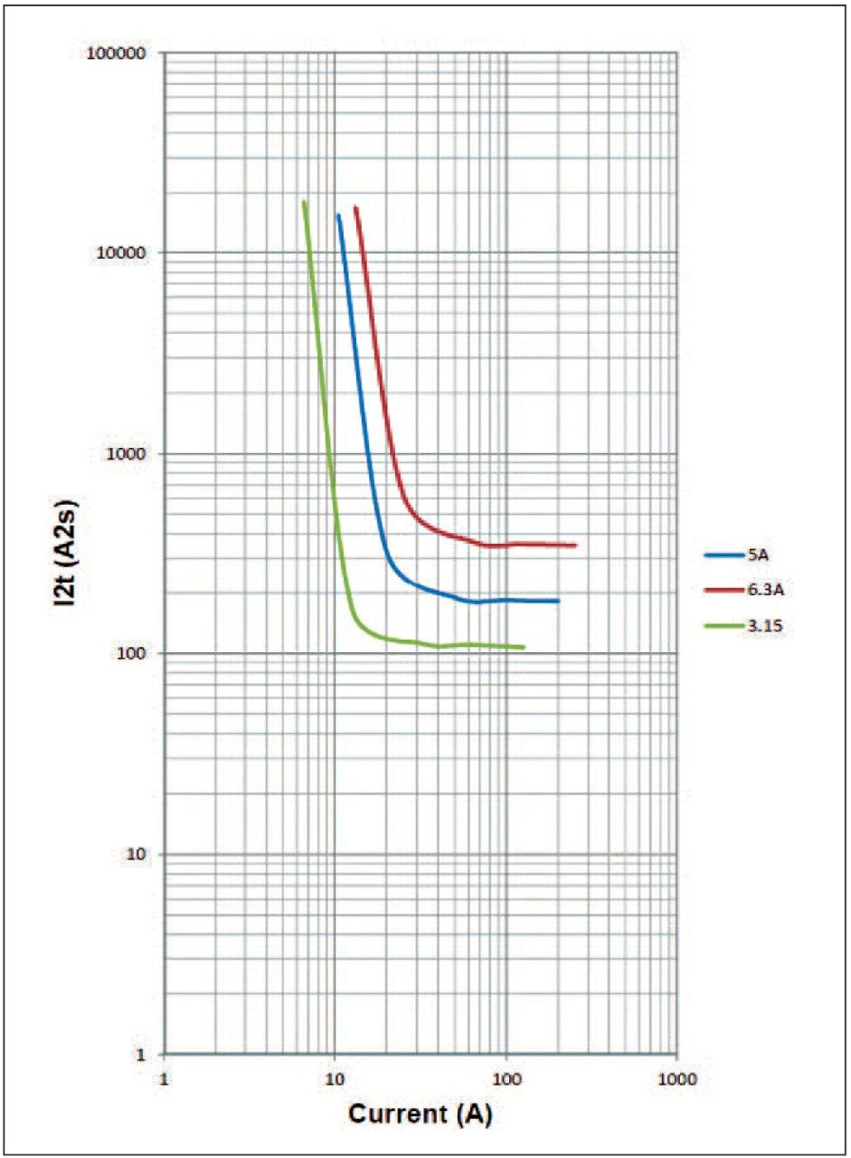
图 1. Time current curve of S505SCH delayed high I2t fuse
Time current curve
The time current curve reflects the relationship between the melting or clearing time of the fuse and the RMS or DC current value. In most published graphics, the characteristic reflected usually refers to the average melting time of the fuse when subjected to a certain current. These curves typically demonstrate the ability to carry 100% of the rated current. They also reflect the ability of the fuse to open at a specified overload point (usually 135% to 300% of the rated value of the fuse) within the maximum open circuit time.
From a design perspective, the time current curve effectively helps engineers specify fuse types or ratings for applications. However, it is recommended to test the fuse samples in practical applications to verify their performance.
Pulse and surge characteristics
Transient surge or pulse current is used to describe the waveform generated by any start-up, surge, or transient current in a circuit. In certain application scenarios, it is normal for pulse currents to occur.
Therefore, it is essential to determine the appropriate fuse capacity size to allow these pulses to pass through without causing disruptive open circuits or fuse component degradation. If the overload state persists, the fuse must open within the limits specified by UL and CSA standards. Surge resistance refers to the function of fuse design and/or classification, which is related to factors such as surge pulse, duration, frequency, etc.
Pulse current may generate thermal energy, which may not be sufficient to cause an open circuit in the fuse, but may lead to component fatigue and shorten the lifespan of the fuse. In order to determine the appropriate capacity and surge tolerance of the fuse, the pulse energy of the circuit should be determined and compared with the time current curve and I2t rating of the fuse. The melting I2t value of the fuse must be greater than or equal to the product of the pulse I2t and the pulse coefficient.
The peak current and decay time define the pulse current characteristics or waveform. Pulses can generate different waveforms, which determines the formula used to calculate pulse energy or I2t. Figure 2 shows how to select the appropriate waveform and its corresponding pulse I2t calculation process.
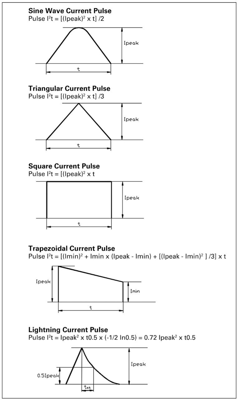
图 2. Pulse waveform and I2t calculation process
Fuse withstand capacity
After calculating the pulse I2t of the circuit, the ability of the fuse to withstand surge pulses without causing thermal stress to the fuse components (which may cause disruptive open circuits) can be determined. Circuit designers need to determine the appropriate fuse capacity size so that the fused I2t value of the fuse is greater than or equal to the product of pulse I2t and pulse coefficient Fp, i.e., I2t fuse ≥ I2t pulse x Fp.
The pulse coefficient depends on the construction of the fuse element. The number and frequency of surge pulses that the fuse can withstand during the service life of the device will affect the fuse components of the "wire in air" structure (such as round tube fuses, 6125 and 1025 series). This structural design utilizes low melting point metals plated or deposited on the main component material to generate the "M" effect. If the capacity of the fuse is not properly determined, low-level pulse current may cause alloys to form between low melting point metals and components, while failing to completely open the components.
A series of pulse currents will eventually generate enough heat to change the resistance, and even permanently open the fuse. Therefore, it is necessary to consider the number of pulse currents that the fuse will withstand.
SolidMatrix fuses (such as 0603FA or 3216FF capacity surface mount fuses) currently do not use the "M" effect on component structures. The component is only affected by the thermal energy of each pulse and usually does not degrade due to the number or frequency of pulses.
Table 1 can be used to determine the pulse coefficient (Fp). For example, for a pulse current with I2t of 0.0823 and a pulse coefficient Fp of 1.25, a fuse with melting I2t greater than or equal to 0.1029 needs to be selected.
·Melting I2t fuse ≥ I2t pulse x Fp
·Fused I2t fuse ≥ 0.0823 x 1.25
·Fused I2t fuse ≥ 0.1029
Please note that the melting I2t value and pulse current value of the compared fuse must be calculated or tested under the same testing conditions; The most important thing is that the peak current magnitude must be the same. For example, if the peak current of the pulse is 15A, the melting I2t of the fuse must be calculated at 15A, and a comprehensive understanding of the electrical characteristics of the fuse at this current value is also required.
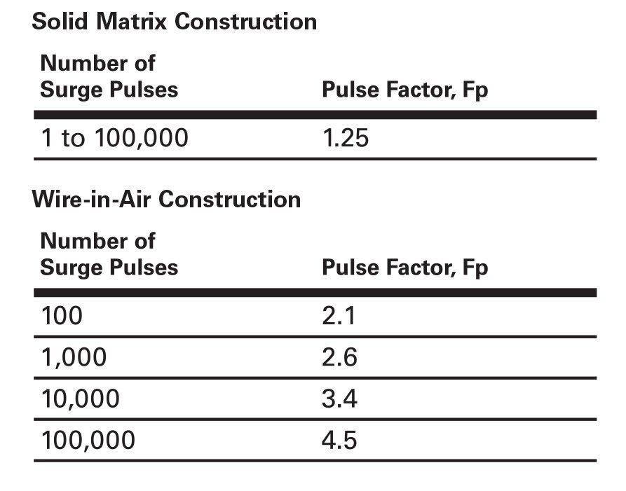
table 1.
pulse coefficient Fp
Available circuit board space
There are various practical sizes of electronic fuses, including miniature fuses (Table 2). The most common circular tube designs are 5x15mm, 5x20mm, and 6.3x32mm (1/4 "x 1 1 1/4"). Miniature fuses are commonly used when there is limited space on circuit boards. For such applications, through-hole plugs and surface mount devices are optional. The standard package sizes for surface mounted fuses are 0402 (1005), 0603 (1608), 1206 (3216), 6125, and 1025. These dimensions are the standard sizes for the entire electronics industry. Through hole axial and radial lead products allow for the installation of fuses on PCBs. Standard round tube fuses with leads can also be installed in this way.
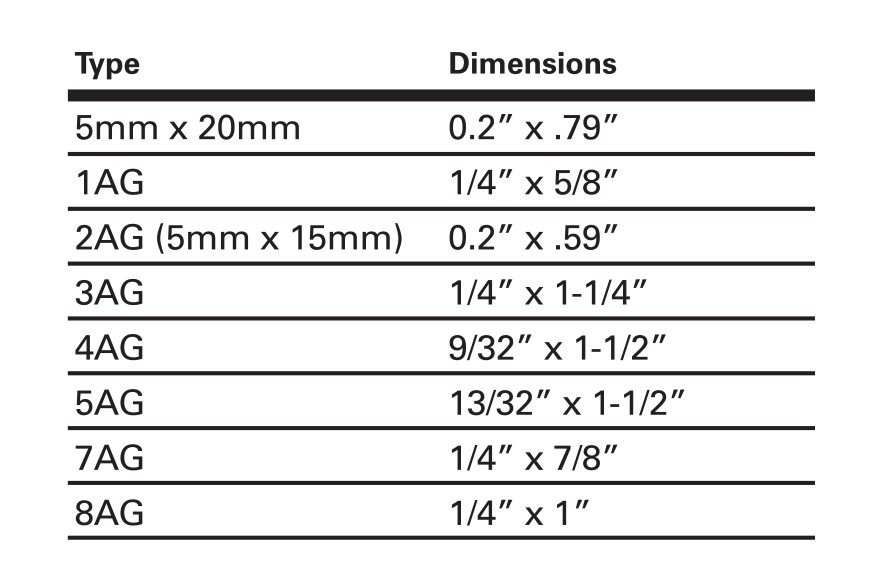
table 2.
The actual size of traditional round tube fuses
standard requirements
For overcurrent devices, there are significant differences in the time current characteristics required by North American UL/CSA and IEC standards. The physical dimensions and materials used are usually similar; However, fuses manufactured according to different standards are not interchangeable because the melting and open circuit times of the components are not the same when they are subjected to the same current value. Therefore, circuit designers must consider that standards around the world may require the use of different fuses.